How is a horizontal tube atmosphere furnace configured for cobalt precursor doping? Expert Setup for Co-N4 Synthesis
Updated 3 months ago
The configuration of a horizontal tube furnace for cobalt-based precursor processing relies on a specific spatial arrangement to facilitate vapor-phase doping. To achieve this, dicyandiamide (DCD) is positioned at the upstream end of the furnace, while the cobalt-based precursor is placed downstream. Under a continuous flow of argon (Ar) carrier gas at approximately 800 °C, the nitrogen-rich vapors from the decomposing DCD are swept over the precursor to induce in-situ nitrogen doping and the formation of stable Co–N4 coordination structures.
The central takeaway is that the furnace acts as a chemical vapor deposition (CVD) reactor where spatial separation between the nitrogen source and the metal precursor ensures that nitrogen-containing vapors interact with the carbonizing framework at the precise moment of structural formation.
Spatial Configuration and Material Placement
The Strategic Importance of Upstream DCD
Placing dicyandiamide (DCD) at the upstream position is critical because it serves as the nitrogen source that must decompose before interacting with the sample. As the furnace heats, the DCD releases nitrogen-containing vapors that are then carried by the gas stream toward the cobalt precursor.
Downstream Positioning of the Cobalt Precursor
The cobalt-based precursor is situated downstream to ensure it is fully immersed in the nitrogenous atmosphere generated by the DCD. This positioning allows the precursor to undergo simultaneous carbonization and nitrogen-functionalization as the vapors pass through its structure.
Establishing the Directional Flow
The configuration depends entirely on the directional flow of the carrier gas to connect the two materials. Without this specific upstream/downstream orientation, the nitrogen vapors would not effectively permeate the precursor, leading to inconsistent doping or poor coordination of cobalt sites.
Environmental Control and Gas Dynamics
The Role of Argon as a Carrier Gas
High-purity argon is used as the primary carrier gas to transport nitrogen vapors and maintain a strictly inert atmosphere. Unlike reactive gases, argon does not interfere with the chemical bonding between nitrogen and the carbon framework, ensuring the purity of the resulting Co–N4 sites.
Maintaining an Oxygen-Free Environment
The tube furnace must be completely sealed to prevent the entry of oxygen, which would cause the aerobic combustion of the carbon matrix. An oxygen-free environment is essential for the pyrolysis process, allowing organic components to transform into a stable carbon framework rather than ash.
Gas Flow Rate and Vapor Density
The velocity of the argon flow determines the residence time of the nitrogen vapors over the cobalt precursor. A precisely controlled flow rate ensures that the concentration of nitrogen-containing species is sufficient to facilitate in-situ doping without bypassing the sample too quickly.
Thermal Processing and Phase Transformation
Optimizing the 800 °C Thermal Field
Operating the furnace at 800 °C provides the necessary energy for both the decomposition of the nitrogen source and the graphitization of the carbon framework. This specific temperature is the "sweet spot" where nitrogen elements are successfully retained within the carbon matrix while inducing the formation of stable Co–N4 coordination.
In-Situ Nitrogen Doping Mechanism
As the cobalt precursor carbonizes, its structure becomes receptive to the incorporation of foreign atoms. The nitrogen vapors react directly with the nascent carbon skeleton, achieving efficient doping through thermally induced chemical bonding rather than simple physical adsorption.
Structural Evolution and Pore Formation
The high-temperature environment facilitates the removal of volatile impurities, which helps in developing a microporous structure. This evolution is critical for exposing active cobalt sites and ensuring the final material has the surface area required for high-performance applications.
Understanding the Trade-offs
Temperature Sensitivity and Material Loss
If the furnace temperature exceeds the optimal range, there is a risk of excessive oxidative loss or the sintering of cobalt particles, which reduces the number of active sites. Conversely, temperatures below 700 °C may result in incomplete carbonization and poor nitrogen integration.
Vapor Distribution Inconsistencies
A common pitfall is the "channeling" effect, where nitrogen vapors flow around the precursor rather than through it. This usually occurs if the precursor is packed too densely or if the tube diameter is significantly larger than the sample boat, leading to non-uniform doping.
Precursor Stability and Decomposition Rates
Different cobalt precursors (such as ZIFs or polyacrylonitrile) have varying decomposition rates. The heating ramp rate must be carefully balanced; heating too quickly can cause the nitrogen source to deplete before the precursor has reached the temperature necessary for doping.
Applying Configuration Principles to Your Goals
How to Apply This to Your Project
To ensure a successful synthesis, tailor your furnace configuration based on your specific material objectives:
- If your primary focus is maximizing nitrogen content: Increase the mass ratio of the upstream DCD relative to the precursor and use a slower heating ramp to extend the vapor exposure time.
- If your primary focus is structural integrity of metal sites: Prioritize a strictly inert argon flow and maintain a stable 800 °C plateau to ensure the formation of Co-N4 coordination without metal aggregation.
- If your primary focus is developing high surface area: Ensure the precursor is spread thinly in the downstream boat to allow maximum interaction with the atmosphere and efficient removal of volatile byproduct gases.
Successful nitrogen doping of cobalt precursors requires a precise synergy between spatial material placement, inert gas flow, and rigorous thermal control.
Summary Table:
| Feature | Setting/Position | Key Function |
|---|---|---|
| Nitrogen Source (DCD) | Upstream | Releases nitrogen-rich vapors during heating |
| Cobalt Precursor | Downstream | Receives vapors for uniform in-situ doping |
| Carrier Gas | High-purity Argon | Maintains inert environment and transports vapors |
| Optimal Temperature | 800 °C | Enables graphitization and stable Co-N4 formation |
| Reactor Setup | Spatial Separation | Ensures vapor-phase interaction at the precise moment |
Elevate Your Material Research with THERMUNITS
Achieving precise Co–N4 coordination structures requires uncompromising thermal control and atmosphere purity. THERMUNITS is a leading manufacturer of high-performance laboratory equipment tailored for advanced industrial R&D. Our specialized Horizontal Tube Furnaces, CVD/PECVD systems, and Atmosphere Furnaces provide the stability and gas dynamics needed for complex processes like nitrogen-doping and carbonization.
Whether you are working on energy storage, catalysis, or advanced ceramics, we offer a comprehensive range of solutions:
- High-Temperature Furnaces: Muffle, Vacuum, Tube, Rotary, and Hot Press furnaces.
- Advanced Systems: CVD/PECVD setups, Dental Furnaces, and Vacuum Induction Melting (VIM) furnaces.
- Components: High-quality Thermal Elements and laboratory heat treatment accessories.
Ready to optimize your synthesis workflow? Contact THERMUNITS today to find the perfect thermal solution for your lab!
References
- Xu Jia, Yujin Chen. Multifunctional Film Assembled from N-Doped Carbon Nanofiber with Co–N4–O Single Atoms for Highly Efficient Electromagnetic Energy Attenuation. DOI: 10.1007/s40820-024-01440-2
Mentioned Products
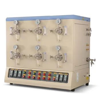
- Multi Position Tube Furnace 1100C for Laboratory Material Research and Advanced Industrial Thermal Processing
- Vertical 1700C Vacuum and Atmosphere Tube Furnace with 80mm Alumina Tube
- 1200°C 10-Zone Split Tube Furnace with Horizontal and Vertical Mounting for Multi-Zone Thermal Gradients and Large Diameter Material Processing
- Compact Vertical Split Quartz Tube Furnace with Stainless Steel Vacuum Flanges for Rapid Thermal Quenching and Controlled Atmosphere Material Processing
- Ten Zone Multi Orientation Laboratory Tube Furnace for 1200C High Temperature Gradient Thermal Processing
People Also Ask
- Why use a tube furnace for oxygen annealing LaCrO3/LaMnO3? Optimize Phase Transition & Magnetic Performance.
- What key role does a laboratory high-temperature tube furnace play in the production of carbon nanofibers? Guide
- How is a laboratory high-temperature tube furnace utilized to research the products of aluminothermic reduction? Advanced Metallurgical Solutions
- What is the role of a laboratory tube furnace in the carbonization process of porous carbon foam (PCF)? Master 3D Synthesis
- What role does a laboratory tube furnace play in the pyrolysis and carbonization of biomass? Optimize Thermal Research.

Tech Team · ThermUnits
Last updated on Jun 03, 2026
Related Products
Multi Position Tube Furnace 1100C for Laboratory Material Research and Advanced Industrial Thermal Processing
Vertical 1700C Vacuum and Atmosphere Tube Furnace with 80mm Alumina Tube
1200°C 10-Zone Split Tube Furnace with Horizontal and Vertical Mounting for Multi-Zone Thermal Gradients and Large Diameter Material Processing
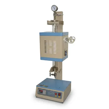
Compact Vertical Split Quartz Tube Furnace with Stainless Steel Vacuum Flanges for Rapid Thermal Quenching and Controlled Atmosphere Material Processing
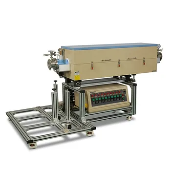
Ten Zone Multi Orientation Laboratory Tube Furnace for 1200C High Temperature Gradient Thermal Processing
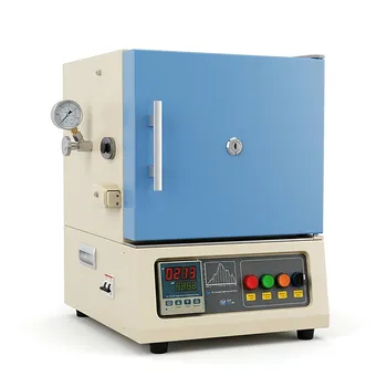
1200C Hybrid Muffle and Tube Furnace for Material Research with Dual Atmosphere Control Quartz Tubes
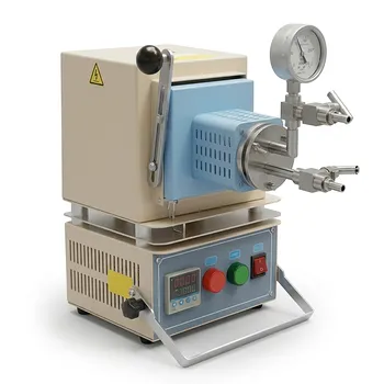
Compact Hybrid Muffle and Tube Furnace for 1000C Controlled Atmosphere Laboratory Material Sintering
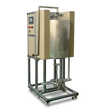
1200°C Atmosphere Controlled Automatic Bottom Loading Furnace with 6 Inch Quartz Tube
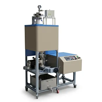
High Temperature 1700C Vertical Tube Furnace for Powder Spherification and Material Sintering
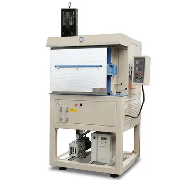
1200C Hydrogen Atmosphere Box Furnace with 5 Heated Sides and 64L Chamber
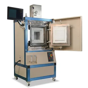
High Temperature Hydrogen Atmosphere Box Furnace 1650C Max Reducing Environment Material Synthesis System 8x8x8 Chamber
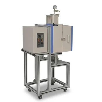
1200°C 5 Inch Vertical Quartz Tube Furnace with Stainless Steel Vacuum Flanges
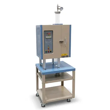
1100°C Split Vertical Tube Furnace with 80mm Quartz Tube and Stainless Steel Vacuum Flanges
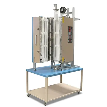
1200C Three Zone Split Vertical Tube Furnace 4 Inch Quartz Tube Stainless Steel Vacuum Flanges
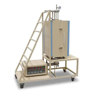
Five Zone Split Vertical Tube Furnace 1200C Max with 4 Inch Quartz Tube and Stainless Steel Vacuum Flanges

High Temperature 1700C Six Zone Split Tube Furnace with Alumina Tube and Water Cooled Flanges
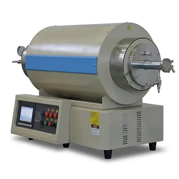
1200C Max Three Zone Tube Furnace 6 Inch OD Max with Tube and Flange
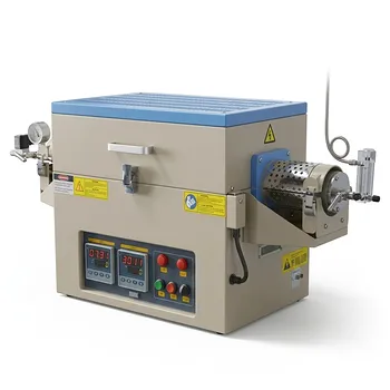
1100C Dual Zone Hydrogen Gas Tube Furnace with Quartz Tube and Integrated H2 Leak Detection System
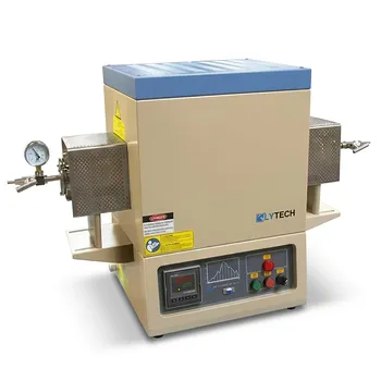
1800C High Temperature Compact Vacuum Tube Furnace with 60mm OD Alumina Tube and Kanthal MoSi2 Heating Elements