How does sample placement affect MOF-CoFe-P quality during phosphorization? Essential Tube Furnace Setup Tips
Updated 6 months ago
Strategic spatial positioning within a tube furnace is the primary determinant of phase purity and structural uniformity in MOF-CoFe-P synthesis. By placing the phosphorus source upstream and the MOF precursor downstream, the carrier gas ensures a continuous, unidirectional flow of phosphorus vapor that penetrates the precursor at a controlled rate. This specific configuration guarantees a consistent depth of phosphorization and prevents the degradation of the delicate metal-organic framework.
The quality of MOF-CoFe-P is dictated by the directional transport of phosphorus vapor; placing the phosphorus source upstream allows the carrier gas to sweep reactant gases evenly across the precursor, ensuring a complete topological transformation into a uniform phosphide phase.
The Mechanics of Directional Phosphorization
The Upstream/Downstream Configuration
The phosphorus source, such as sodium hypophosphite, must be placed upstream of the MOF precursor relative to the gas flow. This arrangement utilizes the carrier gas to transport the phosphorus vapor generated during pyrolysis directly onto the target material.
Consistent Vapor Exposure
As the phosphorus source decomposes, it releases phosphorus-containing gases (like PH3) that must pass uniformly and continuously through the downstream precursor. This ensures that the entire sample surface is exposed to a steady concentration of reactant, leading to macroscopic homogeneity.
Top-Down Chemical Transformation
The spatial layout enables a top-down phosphatization process, where the vapor sweeps across the surface of the MOF nanosheets. This results in a consistent reaction depth across the entire sample, preventing localized over-phosphorization or unreacted metal cores.
Impact on Material Structure and Performance
Preservation of the Carbon Framework
A controlled, directional flow allows for phosphorus atom doping and chemical transformation without destroying the carbon-based framework of the MOF. This is critical for maintaining the structural integrity and conductivity of the resulting CoFeP-m material.
Formation of Uniform Active Sites
Precise placement allows for a complete topological transformation, turning the MOF precursor into a phosphide while maintaining the original morphology. This leads to the formation of uniform active sites, which are essential for high-performance electrochemical applications.
Prevention of Metal Oxidation
The stable inert gas environment, combined with the directional flow of phosphorus vapor, protects the metal components from oxidation. By ensuring the phosphorus vapor reaches the precursor first, the material undergoes chemical transformation rather than unwanted side reactions with trace impurities.
Understanding the Trade-offs and Pitfalls
The Risk of Proximity to the Gas Inlet
Samples placed too close to the gas inlet are more susceptible to trace oxygen impurities. Even in an inert environment, minor leaks or impure gas can form an oxide layer on the sample surface, often indicated by a pink or dark brown discoloration.
Distance and Diffusion Rates
The distance between the phosphorus source boat and the precursor boat directly affects the diffusion rate of the reactant gas. If the boats are too far apart, the vapor concentration may drop, leading to incomplete phosphorization; if too close, the reaction may be too aggressive, damaging the MOF structure.
Thermal Field Non-Uniformity
Tube furnaces have specific thermal gradients where the temperature is most stable at the center. Placing the precursor outside this uniform thermal field can lead to inconsistent sintering kinetics and variations in the crystal phase structure of the CoFeP.
How to Optimize Your Phosphorization Setup
To achieve the highest quality MOF-CoFe-P, you must balance the positioning of your boats with the flow dynamics of your specific furnace.
- If your primary focus is phase purity: Place the phosphorus source at the edge of the heating zone and the MOF precursor at the precise center to ensure the precursor reaches the target temperature while being bathed in a steady stream of vapor.
- If your primary focus is structural integrity: Increase the distance between the two boats slightly to moderate the diffusion rate, preventing a violent reaction that could collapse the MOF’s porous framework.
- If your primary focus is preventing surface oxidation: Ensure the precursor boat is sufficiently downstream from the gas inlet and verify that your carrier gas is high-purity argon to minimize oxygen exposure.
Proper alignment of the quartz boats transforms a volatile chemical reaction into a precise, repeatable manufacturing process for high-quality nanomaterials.
Summary Table:
| Parameter | Recommended Positioning | Impact on MOF-CoFe-P Quality |
|---|---|---|
| Phosphorus Source | Upstream (Relative to flow) | Ensures continuous, unidirectional vapor transport. |
| MOF Precursor | Downstream (Thermal Center) | Guarantees uniform temperature and reactant exposure. |
| Boat Distance | Optimized Gap | Controls diffusion rate to prevent structural collapse. |
| Inlet Proximity | Sufficiently Downstream | Prevents surface oxidation from trace oxygen impurities. |
Achieve Precise Phosphorization with THERMUNITS
At THERMUNITS, we understand that high-performance material science requires exact thermal and atmospheric control. As a leading manufacturer of high-temperature laboratory equipment, we provide the tools necessary for advanced R&D, including:
- Precision Tube Furnaces & CVD/PECVD Systems designed for uniform gas flow and vapor transport.
- Vacuum & Atmosphere Furnaces to eliminate oxidation during sensitive synthesis.
- Muffle, Rotary, and Hot Press Furnaces for diverse heat treatment needs.
- Specialized Solutions including Dental Furnaces, VIM systems, and Thermal Elements.
Whether you are synthesizing MOF-derived phosphides or developing new catalysts, our equipment offers the stability and uniformity your research demands.
Ready to optimize your lab’s thermal processing? Contact us today to discuss your requirements and see how our tailored solutions can enhance your material quality and research efficiency.
References
- Lukuan Hao, Shuiyun Shen. Bimetallic MOF-derived CoFe phosphide nanomaterials imparted efficient synergism for oxygen evolution reaction. DOI: 10.1088/1742-6596/2840/1/012015
Mentioned Products
- Dual Zone Quartz Tube Furnace with 80mm Diameter 1200C Max Temperature 3 Channel Gas Mixer and Vacuum Pump System
- 1100°C High Temperature Quartz Chamber Furnace 8 Inch OD with 7.6 Liter Capacity and Vacuum Atmosphere Capability
- 1100°C Large Diameter Quartz Tube Furnace with 24 Inch Heating Zone and Water Cooled Flanges
- 1200°C 5 Inch Vertical Quartz Tube Furnace with Stainless Steel Vacuum Flanges
- Compact Vertical Split Quartz Tube Furnace with Stainless Steel Vacuum Flanges for Rapid Thermal Quenching and Controlled Atmosphere Material Processing
People Also Ask
- How do dual-zone quartz tube furnaces achieve controllable material preparation? Optimize Perovskite VD Processes
- Why is a dual-zone tube furnace necessary for ReO3-doped Cu2Te CVD? Essential for precise precursor synchronization.
- What are the technical advantages of using a dual-zone tube furnace system? Optimize Nanomaterial Growth & Stoichiometry
- Purpose of the reverse gradient step in CVT growth? Master Crystal Purity with Dual-Zone Furnaces
- What are the technical advantages of using a dual-zone tube furnace for growing large PdCoO2 crystals via CVT? Expert Tips

Tech Team · ThermUnits
Last updated on Apr 14, 2026
Related Products
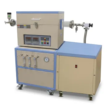
Dual Zone Quartz Tube Furnace with 80mm Diameter 1200C Max Temperature 3 Channel Gas Mixer and Vacuum Pump System
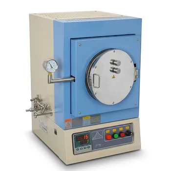
1100°C High Temperature Quartz Chamber Furnace 8 Inch OD with 7.6 Liter Capacity and Vacuum Atmosphere Capability
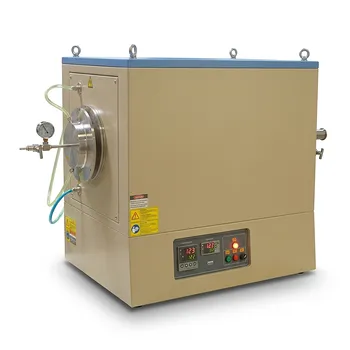
1100°C Large Diameter Quartz Tube Furnace with 24 Inch Heating Zone and Water Cooled Flanges
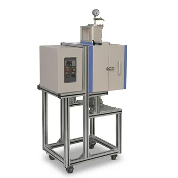
1200°C 5 Inch Vertical Quartz Tube Furnace with Stainless Steel Vacuum Flanges
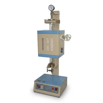
Compact Vertical Split Quartz Tube Furnace with Stainless Steel Vacuum Flanges for Rapid Thermal Quenching and Controlled Atmosphere Material Processing
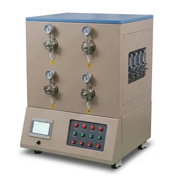
High Throughput 1200C Four Channel Tube Furnace with 3 Inch Quartz Tubes for Multi Zone Annealing and Material Research
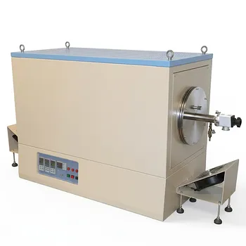
1100°C Three Zone Tube Furnace with 8.5 to 11 Inch OD Quartz Tube and Vacuum Flanges for Large Wafer Processing
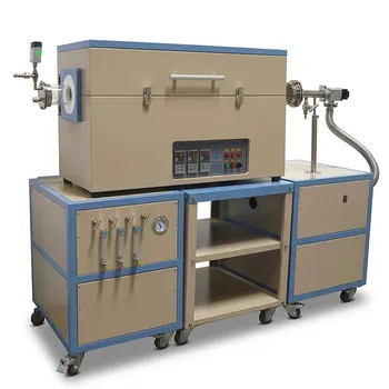
Three Zone Quartz Tube Furnace with 3 Channel Gas Mixer Vacuum Pump and Anti Corrosive Vacuum Gauge
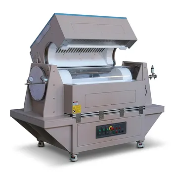
Three Zone Tube Furnace with 11 Inch or 15 Inch Quartz Tube and Hinged Flanges for Vacuum Atmosphere Heat Treatment
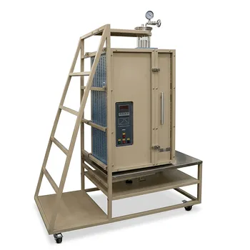
Split Vertical Tube Furnace with 1200C Quartz Tube and Stainless Steel Vacuum Flanges for Rapid Thermal Processing
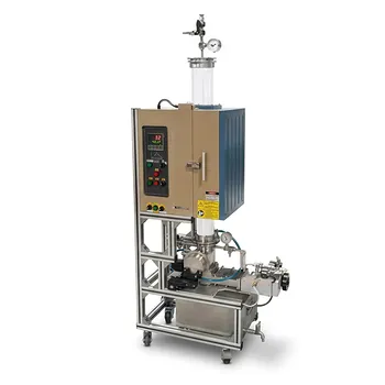
1200C High Temperature Atmosphere Controlled Vertical Quenching Tube Furnace with 4 Inch Quartz Tube
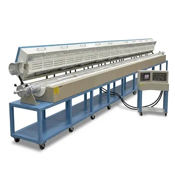
12 Zone Ultra Long Split Tube Furnace with 20 Foot Quartz Tube and 1100C Max Temperature
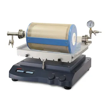
High Temperature Rocking Tube Furnace with Quartz Tube and Vacuum Flange for Materials Synthesis
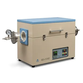
Single Zone Tube Furnace 5 Inch Quartz Tube 36 Inch Heating Zone Vacuum Flanges
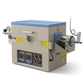
1100C Dual Zone Hydrogen Gas Tube Furnace with Quartz Tube and Integrated H2 Leak Detection System
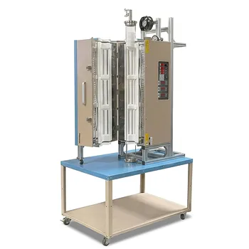
1200C Three Zone Split Vertical Tube Furnace 4 Inch Quartz Tube Stainless Steel Vacuum Flanges
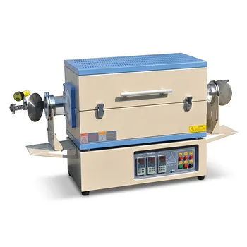
Three Zone Tube Furnace with 24 Inch Heating Length and Hinged Flange Quartz Tube System
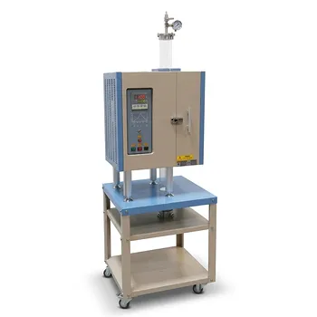
1100°C Split Vertical Tube Furnace with 80mm Quartz Tube and Stainless Steel Vacuum Flanges
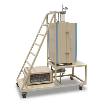
Five Zone Split Vertical Tube Furnace 1200C Max with 4 Inch Quartz Tube and Stainless Steel Vacuum Flanges